

Lighting for Intelligent Transport Systems (ITS)
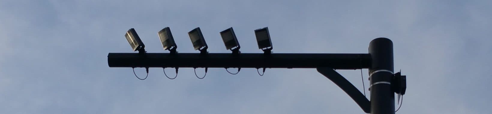
LPR/ ANPR – The Key Element
LPR = License Plate Recognition
ANPR = Automatic Number Plate Recognition
LPR/ ANPR refers to the activity of capturing a high-quality image of a plate (car number plate, vehicle license plate or similar) and the intelligent software process of reading and recognising the alpha numeric characters of the plate. This White Paper will deal exclusively with capturing the plate.
In order for LPR/ANPR systems to work effectively, it is essential that a high-quality image of the plate is captured 24/7 365 days a year in all operating, lighting, weather and environmental conditions.
You have to adopt a systems approach when designing an LPR/ANPR system. The quality of the image is based on the combination of the key optical elements being camera, lens and any filtering used. Critically, the effective performance of these elements rely on the right quantity and quality of lighting being deployed. Without light, the optical elements cannot function effectively or consistently.

Figure 1 – Key elements of capturing the plate; (left to right) camera, lens, filter, light
And the old adage in computing applies: Garbage In = Garbage Out. You need to get great images if you
want an effective system.
Common Global Challenges of Capturing the Plate
You need a system that reliably and consistently overcomes the problems of getting an excellent image of the plate. The common challenges include:
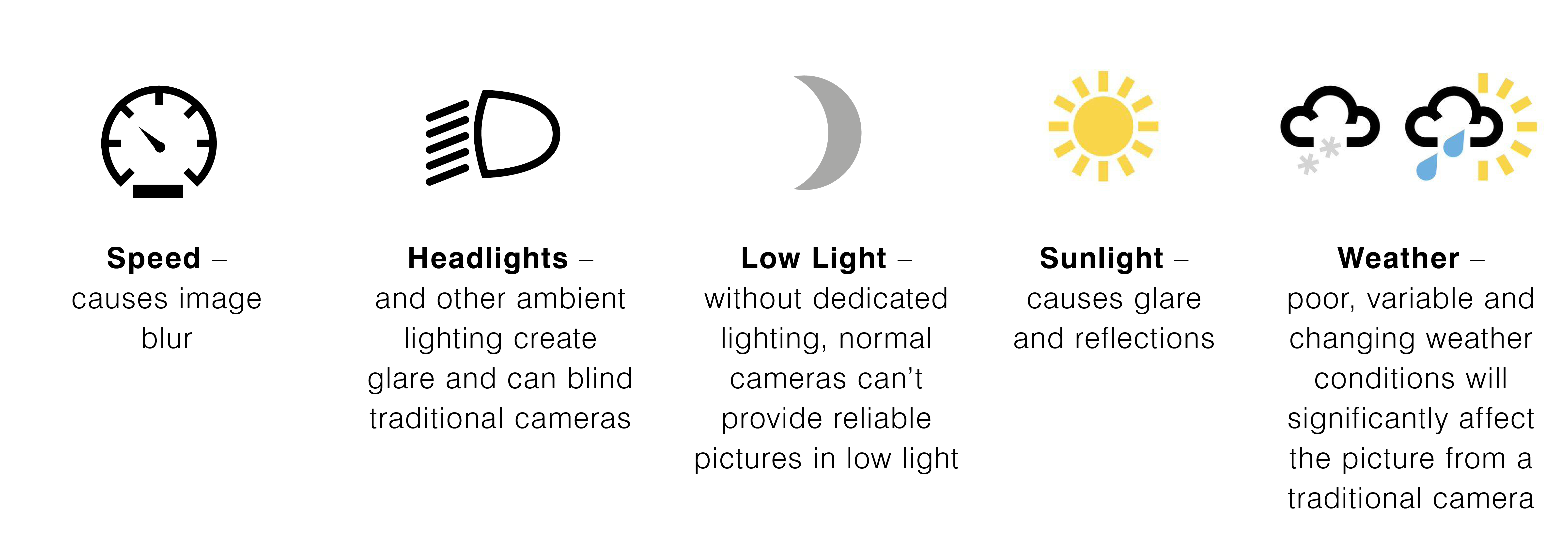
Speed, headlights, extremes of lighting conditions (from low light at night to extremely bright daytime operation), reflections and direct glare from the sun and changeable weather conditions are common to installations all around the world that want to capture the plate. There are specific challenges as a result of the wide variation of plates from around the world and we have addressed these more fully in Specific Challenges of Capturing the Plate.
The Raytec ‘Magic Formula’
The Raytec ‘Magic Formula’ has been developed over many, many years of hands-on practical experience and helps to deliver the correct optical and lighting set up to capture the plate. Of course, final performance depends on the actual quality and performance of the individual elements chosen and we would always recommend actual testing of any system in real-life operating conditions prior to wide scale deployment. However, in general terms, the Magic Formula helps to deliver the right results.
The fundamentals of the Magic Formula are:
- Choose good quality components.
- Test the products in real-life situations in the relevant operating conditions.
- Set a fast shutter speed on the camera to overcome motion blur.
- Use minimum camera gain to reduce unwanted noise which will affect Optical Character Recognition
(OCR). - Increase gamma setting to maximise contrast of the plate.
- Set a high f-stop on the lens to eradicate unwanted light and to manage changing light / weather
conditions. - Use a narrow band pass filter to block any unwanted light. Match your narrow band pass filter to your
light source. - Critically, use additional, purpose-designed, dedicated lighting.
- Correctly mount lighting and camera both with reference to each other and with regards to the plate.
It is all about combining the right quality, quantity and wavelength of light dependent on the type of plate that you want to capture. The most commonly used light source is 850nm Infra-Red illumination.
Camera Set-Up
So, let’s consider the common challenges one by one. The first being speed.
Fast Shutter Speed to Combat Motion Blur
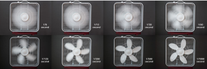
Figure 2: The effects of running a faster shutter speed
You can see the effect/benefit of running a faster shutter speed from the pictures above. The camera is better able to freeze the motion of the fan with a faster shutter speed. When pausing the image, the only time that the fan does not appear blurred at all is when running at 1,000th second shutter speed which is coincidentally what we recommend for normal LPR/ANPR applications. There is a trade-off though. A faster shutter speed allows less usable light to pass to the camera sensor. This can be clearly seen in the next set of images.
Fast Shutter Speed and Light
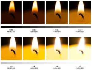
Figure 3: The effect of altering the shutter speed of the camera
These images emphasise the fact that the faster the shutter speed, the less usable light the camera has.
- At 1/2 second exposure the camera is receiving too much light, there is glare and the focus of the image is poor.
- At 1/30th second exposure the glare has disappeared, and the focus is good.
- By 1/250th second there is not enough light for the camera to provide a usable picture.
So, there is clearly a trade-off between shutter speed and usable light. Fortunately, it is a simple linear law (i.e. directly proportional) so it is very easy to calculate, understand and compensate for the effects of running a faster shutter speed on the amount of available/usable light.
Now let’s consider the impact of speed and motion blur in a typical traffic application;
- A car travelling at 70mph/112kmh travels 104ft/31.2m in a single second.
- With a shutter speed of 1/50th second, the car moves 62cm (24”) every time the camera shutter is open – and a very blurry image would be the result.
- With a shutter speed of 1/1000th second, the car only moves 3cm (1”) every time the camera shutter opens which means that the camera can produce a clear crisp image – providing there is still enough light available.
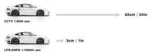
Figure 4: A faster shutter speed results in less motion blur
So, although increasing the shutter speed reduces the amount of motion blur the down side is that it also reduces the amount of light that reaches the cameras sensor. This needs to be factored into the overall design.
Other Camera Settings:
We can only speak generally here, since it is difficult to give absolute advice due to the wide variety of cameras available in the market. However, in general terms, The Raytec Magic Formula recommends two additional camera adjustments in addition to a fast shutter speed;
Lower AGC to Reduce Noise
For the purposes of LPR/ANPR and specifically to reduce noise in the picture to provide the best possible image for OCR processing, we recommend setting the AGC as low as possible on the camera. Reducing the AGC helps to significantly reduce noise in the picture but also has the effect of reducing the overall brightness of the picture, so there is a compromise.
A balance has to be established. Typically, we would recommend setting the AGC of the camera at approximately 1/3 to 1/2 of its maximum setting. When we look at the ‘Big Lighting Challenge’ later in the paper, we will disregard the effect that lower AGC has on the overall lighting requirements, but in essence a lower AGC would require additional lighting to provide the same brightness of picture created when using a higher AGC setting.
Gamma Setting to Improve Contrast
In general terms, having a higher Gamma setting improves the contrast between extremes of black and white elements of the picture which is exactly what we want for LPR/ANPR in many cases. Typically, we would set the Gamma to 1 to maximise this contrast.
Some camera manufacturers may not refer directly to Gamma settings. They may use other terms to describe similar features such as contrast, sharpness etc. If the Gamma setting does not readily appear on the menu of your chosen camera, contact the manufacturer directly to understand how to achieve a greater contrast at the extremes of the black and white scale.
Lens and Filtering
Headlights, other ambient lighting, changing lighting conditions (from low lighting levels at night to extremely bright lighting conditions during the day), glare and reflections (from the sun) and variable weather conditions are all addressed through a combination of lens settings, filter and lighting.
Aperture
For traditional video surveillance applications, lenses will be set with a lower f-number (f-stop) in order to maximise the amount of available light, especially at night. The lower the f-stop of a lens, the more light the lens is able to capture and allow to pass to the camera sensor. However, in turn this creates a shorter depth of field.
On the other hand, the higher the f-stop, the less light that passes through the lens, but a bigger depth of field is produced. By selecting a bigger f-stop setting for the lens, and therefore closing its aperture, the amount of glare from headlights, the sun and other ambient lights which might blind the camera, will be reduced.
Changing the f-stop on a lens is not a linear law. It is a square law. Move from an f2 aperture to an f4 aperture and you have not halved the amount of light available, you have reduced it by 75%. The image below shows the effect of changing the f-stop of the lens. All other factors remain constant.
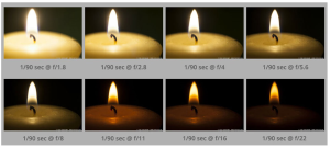
Figure 5: Effects of changing the f-stop of a lens
- At f1.8 there is slight glare and poor focus and poor depth of field in the picture.
- At f5.6 the picture and focus are good with a good depth of field.
- At f22 the picture is unusable as a result of insufficient light.
So, the higher the f-stop, the better the depth of field and the better the focus – but less light is available.
Closing the aperture of the lens in order to capture the plate has a lot of advantages such as reducing the impact of headlights, the sun, reflections etc and significantly improve the depth of field of the picture and the focus but it means we need to provide additional light where we want it i.e. on the plate!
Normally we recommend a minimum f-stop of f5.6 but that reduces the amount of light passing to the camera lens by a factor of 16 when compared to an f1.4 lens.
Narrow Band Pass Filter
Another vital trick we have learnt over the years is the addition of specialist, narrow band pass filters. Carefully selecting a filter for your lens (which must match the wavelength of the specialist lighting being used) helps to filter out and reduce the effect of headlights, the sun and other ambient lights. By choosing the right filter, there should be minimal negative effect on the dedicated LPR/ANPR lighting you are using, but a significant and beneficial effect on reducing the effect of unwanted light, reflections and glare. Please refer to the graph below.
A correctly selected filter will only have a marginal negative effect on the ‘Big Lighting Challenge’, so we can disregard this as part of the calculations.
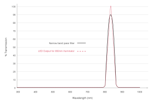
Figure 6: LED Output and Bandpass Transmission
Practical Mounting Tips
A vital practical tip is to mount your lighting as closely as possible to the camera for retroreflective plates. The closer the co-location means that more light will be usable and useful for the camera. Even small adjustments to this can have a big impact on the amount of light required.
Critically, for retroreflective plates, mount the camera/light combination at an incidence angle of less than 35 degrees. An incidence angle of greater than 35 degrees could destroy the benefits of the retroreflective plate and render the system ineffective.
The Big Lighting Challenge of LPR/ANPR
So, from our Magic Formula and the main set-up we have advised for both the camera and the lens, we can now evaluate the impact those have on your lighting requirement. The two key elements of the magic formula which affect lighting are:
- Camera Settings: 1,000th second shutter speed • Lens Settings: f5.6
The Mathematics
So, the challenge when moving from a traditional surveillance set up to a specific LPR/ ANPR set up is summarised:
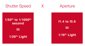
The Raytec Magic Formula states we need a high shutter speed to reduce motion blur and a bigger f-stop to overcome unwanted light sources. Combined however, available light is reduced by a factor of 1/320th. This is why we need the right targeted lighting designed into a system when we want to capture the plate.
Fortunately, most plates are highly retroreflective and therefore the amount of light required to illuminate them correctly is small when compared to other objects. That is why in a traditional video surveillance system plates are often over illuminated and ‘white-out’ at night, because they are so reflective.
The level of light required will depend on the specification of the plate (which we cover in more detail in chapter 8), but you must also take into account the fact that you require 320 times more light to overcome the effect of shutter speed and aperture adjustments. We would therefore typically apply a multiplying factor to Raytec’s normal quoted distances to calculate effective distances for LPR/ANPR. This is something Raytec would be happy to assist you with for your application.
This will always be a rough ‘rule of thumb’ estimate and we would always recommend testing of your overall system.
Practical Tips when Specifying Lighting
Distance and Angle
When designing a number plate capture system, you need to consider the distance to the target, the horizontal field of view and the camera mounting position.
Light obeys the inverse square law which states that the intensity of a diverging light source is inversely proportional to the square of the distance from that source. As light travels away from a point source it spreads both vertically and horizontally and therefore intensity decreases – not as a linear function, but as a square function. This means that if light travels double the distance, there will not be ½ power intensity (which would be a linear law) but there will be a ¼ of the original power intensity (a square law).
In addition, when designing your lighting scheme, you need to consider:
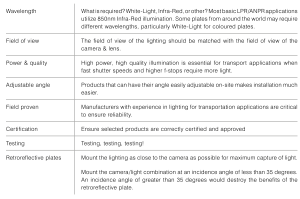
Figure 7: Key Considerations when designing your lighting scheme
Infra-Red Lighting
An Intelligent Transport System will normally operate 24 hours, 365 days a year. To provide high quality image capture the system must be able to cope with a wide range of lighting conditions. A standard surveillance camera simply cannot cope with these changing conditions. To overcome this difficulty the system must provide a reliable and consistent level of illumination regardless of any other lighting factor.
Infra-Red lighting is generally the most commonly used for LPR/ANPR applications particularly if there is little colour information required from the capture of the plate. Some systems will require White-Light to obtain additional information from the plate but then care must be taken to avoid blinding the occupants of the vehicle, particularly the driver.
For Infra-Red systems, to allow the camera to blank out any ambient light sources it is fitted with a narrow band pass filter which is normally attached to the camera lens. Only light of a certain wavelength can pass through. The spectral response of the band pass filter must match the spectral output of the Infra-Red source used. It is normal for number plate capture system to use an 850nm light source. This should be mounted adjacent (as closely as possible) to the camera to take full advantage of the retroreflective properties of the plate.
Challenging Environmental Conditions
ITS applications are typically deployed in very challenging environments. You need to ensure that the lighting has proper certification for the specific application, and you need to ensure that the lighting is designed for extreme environments and operating conditions

Figure 8: Environmental challenges for ITS applications
Advanced Lighting: Additional Features
When specifying lighting for LPR/ ANPR applications, in addition to the basic tips offered above, specifiers should consider some of the additional features and benefits offered by more intelligent, smart lighting solutions. These help to improve the performance of the system, and also provide time and cost savings during installation, commissioning, operation and maintenance.
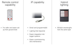
Figure 9: Additional features to consider when specifying lighting for LPR / ANPR applications
Pulsed vs Constant Lighting
Traditional lighting is on 100% of the time required since the ‘user’ of the light (typically people) want it to be constantly available. However, as we know, for LPR/ANPR applications the camera is not constantly capturing images, it is effectively taking a 1,000th of a second snapshot every frame.
Synchronised Illuminators
Using an example, if the camera shutter is only open for 1 millisecond every 50 milliseconds, then the camera shutter is only open for 2% of the time. Due to the fast switching speeds of LEDs it is possible for the LEDs to be synchronised with the camera and only turn on (or pulse) when required. We can make the pulse slightly longer than the shutter opening to ensure the LEDs are at maximum power and all available light is captured when the shutter is open. This is generally 0.5 milliseconds at the start and end of each cycle, so 1 millisecond in total. This means the illuminator will only be on for 4% of the time.
As number plate capture systems run 24 hours a day, 365 days a year, this reduces the cost of ownership and increases the lifetime of the product. The LEDs can also be overdriven and able to deliver more power.
Why Pulse?
Let’s take a look at the benefits of pulsed illumination in a little more detail;
- More power: LED Overdriving – When an illuminator is pulsed at a low duty cycle, it is possible to increase the light output by overdriving the LEDs. The LEDs can be driven harder because they are only on for a very short amount of time. The maximum increase is down to the particular LED used, the time the LED is illuminated vs the duty cycle and the limitations of the drive circuit. Typically, over driving the LEDs can deliver as much as 3-5 times more power from the same package. This can help deliver longer achievable distances or brighter lighting at the same distance or enable you to use a smaller illuminator to achieve the required distance (and therefore reduce capital costs).
- Lower Consumption – During pulse operation, an LED illuminator is only on for short bursts of time and is actually switched off for much longer periods. This can help to significantly reduce overall power consumption. If power saving is the primary focus, power consumption can be reduced by as much as 95% if the LEDs are pulsed, without overdriving or by 75% if they are driven at 5 times pulse power.
- Lower Operating Temperature – In pulse operation, your illuminator may only be on for 1/20th of the time and off for 19/20th. This means that it will run very cool when compared to an illuminator running in continuous mode. This has the benefit of considerably lowering its normal operating temperature. This means in high operating conditions (including high ambient temperatures in certain countries) pulse operation can provide a safer operating mode for your illuminator thereby increasing reliability.
- Lower Visual Impact – Although it may be more important for white light systems, pulsing has the additional benefit of reducing the visual impact of the illuminator for drivers.
- Increased Functionality – In addition to the savings in operating and capital costs, using pulsed lighting that is specifically designed for LPR/ANPR applications does offer other significant benefits.
Different pulse power levels or different wavelengths of light can be used to provide better capture of the same plates, or of different plates. You may also be able to capture other objects which require different lighting wavelengths or power levels including driver recognition, passenger counting, vehicle recognition, detecting car permits or other vehicle markings.
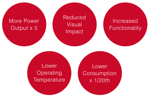
Figure 10: The benefits of pulsed lighting
Raytec offer both pulse and constant lighting products so we are happy to advise which is most appropriate for your specific application.
Pro-Tip – Constant lighting is potentially easier to design and install. Pulsed lighting requires a more complex installation but can provide significant cost savings and performance advantages.
All-in-One vs Separates
There are a number of integrated, ‘All-in-One’ LPR/ANPR cameras available in the market. Alternatively, System Integrators may prefer to take full control and design their own system using separate components.
Think back to the 1970’s and 1980’s with the introduction of All-in-One music systems which offered an alternative to the separate audio components that traditionally music lovers would select and connect themselves. The same arguments apply in the ITS world with regards to LPR/ANPR.
Of course, both solutions are viable and have their place in the market. Some applications may demand one route or the other, but it is important to consider the merits of both:
- All-in-One – This type of system potentially provides easier specification; easier integration and it may be easier to source. However, the downsides are that overall performance may be compromised, there is less flexibility and a narrower choice of products and you could be tied into a specific software
supplier. Servicing and maintenance of these systems is potentially more expensive and challenging; if one part of the system fails, it renders the whole unit unusable. - Separates – By using separate components it means you can meet specific requirements, have ultimate flexibility, use best in class for each element of the system, integrate with a wider choice of 3rd party software suppliers, meet the needs of more demanding applications and have greater control across the whole system. Servicing, maintenance and upgrades could be easier since individual elements of the system can be replaced. Sourcing and integration of the separate components may be more difficult and overall installation costs may be higher but should be compared to total lifetime cost of the system.
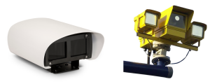
Figure 11: Example of an All-in-one (left) and Separate (right) solution
The choice is a commercial one dictated by the needs of specific projects or specifications. The ‘All-inOne’ route may be perceived as the easier one, but for more demanding or specialist applications or where Integrators are looking to offer their customers something more bespoke and specific and, as a result, enjoy a closer relationship with their customers, then the ‘Separates’ approach should be considered.
For low speed applications which do not require a very high accuracy rate, then ‘All in One’ systems are more than capable. For more extreme high speed, long distance applications, or challenging operating/climatic conditions, then the ‘Separates’ approach is most likely the only viable one.
The Common Challenges and Solutions – Summary
To summarise, the challenges of capturing the plate include overcoming:
- Speed and motion blur of fast-moving objects
- Unwanted light, glare and reflections from the sun, headlights and other light sources
- Extremes of changing lighting conditions for 24/7 operation, from bright sunlight to low/no light
- Changing weather and environmental conditions
We have shared the key elements of the Raytec Magic Formula to overcome the challenges above:
- Set a fast shutter speed on your camera, typically 1,000th second
- Set a high f-stop on your camera, typically f5.6 or higher
- Use a narrow band filter which matches your additional lighting
- The importance of having the right quantity, quality and wavelength of light – typically 850nm.
Specific Challenges of Capturing the Plate
Now let us consider some of the specific issues related to more challenging plates. In many cases, the Raytec Magic Formula (or some subtle variant thereof) will still apply. In certain cases, specific lighting designs and solutions may be required and of course, with our wealth of knowledge and practical experience, we would be delighted to assist in the design of such systems.
Different plates from around the world create their own specific challenges and issues:
- Material – Most plates are made from retroreflective material (either specific plastics or paints) but some aren’t. Many are made of plastic, some metal.
- Size & Quantity – The size of the plate is important. Some states in the US allow only a single plate to be fitted which can be a challenge.
- Colour – The colour of the lettering and background will affect the choice of lighting (wavelength) to be used.
- Font – The wide variety of font sizes and styles can be challenging. Some countries like the Netherlands have adjusted some of the letters on their plates specifically to improve recognition rates (see the ‘R’ at the end of the Dutch plate (figure 12 below) – they have modified the font to avoid confusion with other letters).

Figure 12: Plates from around the world; (left to right) USA, UK, Saudi Arabia, Netherlands
In addition to the alpha-numeric information of the actual plate, there may also be other information or graphics or plates which are deliberately modified which make the task of capturing and recognising even more challenging:
- Additional Information – like tax or registrations dates or additional geographic information such as
country or state information - Additional Graphics – many US states have images specific to them (e.g. oranges for Florida etc)
- Vanity plates with unauthorised fonts, spacing, lettering and images
- Unauthorised plates which again may contain graphics, colours and fonts which are non-standard, and some people may deliberately use certain materials in an attempt to combat LPR/ANPR systems
Variations in the material composition, size, colour and font of the plate will impact the effectiveness of the system and the specific choice of lighting and filtering techniques used.
Because plates come in a large number of different styles, it makes it difficult to design a single, standardised system for global deployment. Typically, the UK, most parts of Europe and many parts of North America, use high quality, retroreflective plates which work very well with traditional IR (typically 850nm wavelength) lighting. In other parts of the world the quantity and consistency of plates may be more variable.
So, why can plates be so variable? There are 3 typical types of reflection that happen when light hits an object and is reflected. Some of the light is also absorbed, not reflected, by the object depending on its physical/chemical make-up.
The way that any object reflects light is a function of its shape and its material of construction.
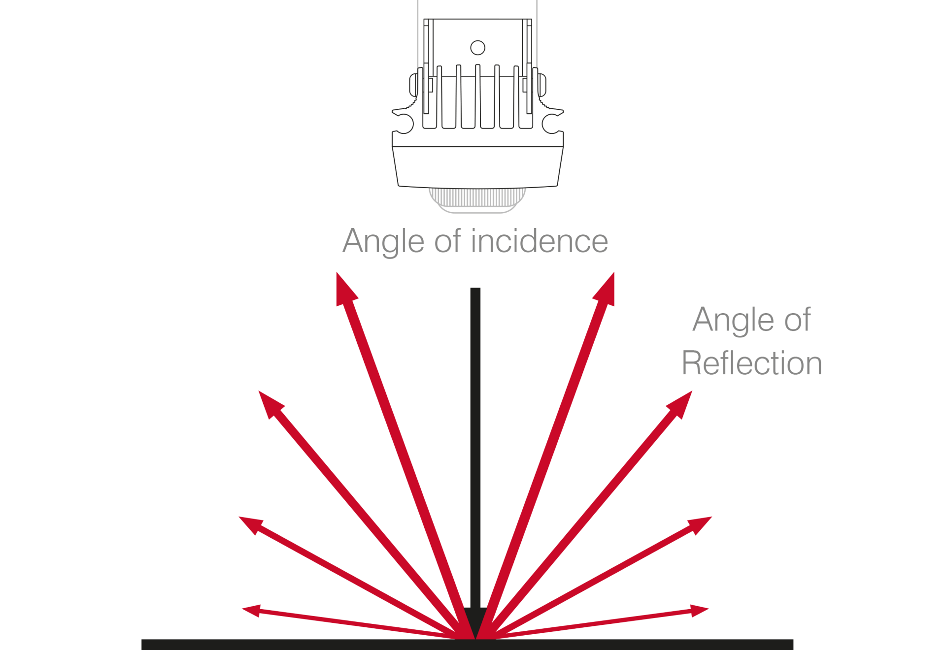
Diffuse reflection
Diffuse reflection is when the object reflects light in all directions to varying degrees. This is the most common type of reflection and the vast majority of objects reflect light in this way. The direction in which the light is reflected depends on the shape and material of the object, the angle of the incident light and the quantity of light depends on how much light is absorbed by the material. The overall amount of light reflected can be quite low (less than 20%) and therefore more light is required to illuminate diffuse materials well.
Specular reflection
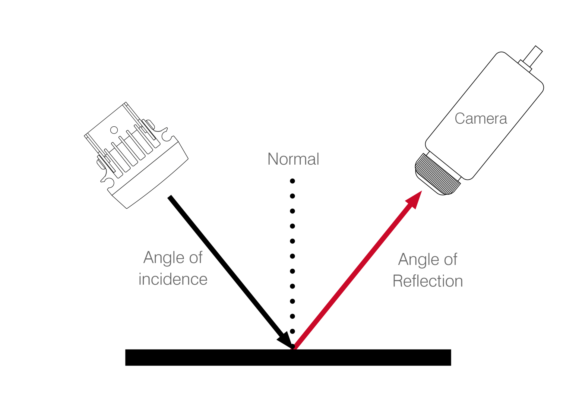
The least common type of reflection is specular reflection which involves the angle of incident light and the angle of reflected light being the same. The figure shows the light bouncing off the object and continues to travel away from the source – and in this case the camera too. No light is reflected back for the camera to generate an image unless the angle of incident light is perpendicular (90°) to the object. Typical examples of specular reflection are mirrors, some very shiny metal objects, very calm flat water. This type of reflection can normally be ignored for LPR/ANPR.
Retroreflection
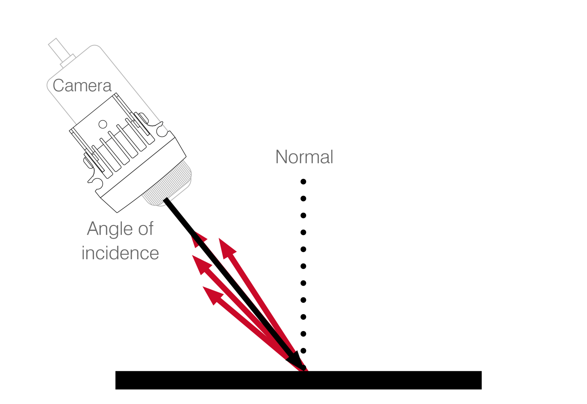
More common than specular, though a manmade invention, are items that are retroreflective. The light returns in the same direction that it strikes the object which means most of the light is usable by the camera. Examples of retroreflective object are number/license plates, road signs, reflective items worn by cyclists, road workers etc.
Retroreflective Plates
As the name suggests retroreflective plates are retroreflective.
We can obtain a clear picture of the plate when using dedicated equipment, but in normal video surveillance applications they can easily be over illuminated because too much light is reflected back to the camera.
These plates are highly efficient and effective reflectors and most of the light is reflected directly back to the source – and hence back to the camera.
Location of camera and light is critical for retroreflective plates. They should be co-located as closely as possible and at an angle of incidence to the plate of less than 35 degrees. Otherwise the benefits of the plate’s retro-reflectivity will be lost.
This is the most common type of plate and is standard in UK, most parts of Europe and many parts of North America.
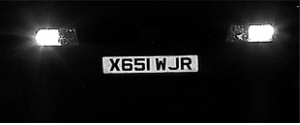
Figure 16: An example of a retroreflective plate
Non-Retroreflective Plates
Less common, non-retroreflective plates reflect light like a diffuse reflector. This means that much less light is reflected back to the source and the camera. This may be as little as 20% of the incident light.
Much more light is needed and co-location of camera and lighting is less critical.
These types of plate are becoming increasingly less common.
Whilst Part 1 of this White Paper has focussed on lighting for LPR/ ANPR systems and the challenges surrounding effective capture of the plate, Part 2 will concentrate on lighting for other OCR applications and vehicle and driver identification. This will explain how an effective lighting system can aid data analysis even further in applications such as traffic control, crime and surveillance.
About the Author
Tony Whiting is Chairman of The Raytec Group of Companies.
Raytec are recognised as world leaders in the field of LED illumination for security and safety. He has nearly 30 years practical, hands-on experience within the lighting market developing and delivering innovative solutions with the sole mission of improving the night-time capabilities of the professional CCTV/ surveillance industry.
Raytec has been involved in designing and delivering some of the largest lighting projects for ITS including major LPR/ANPR systems around the world.
If you would like to make any comments on this article or have any additional questions, please do not hesitate to make contact: tony.whiting@rayteccctv.com
No part of the publication may be reproduced in any material form
(including photocopying or storing in any medium by electronic means
and whether or not transiently or incidentally to some other use of this
publication) without the written permission of the copyright holder, Raytec